|
|
|
|
|
|||
|
|
|
|
|
|||
|
|
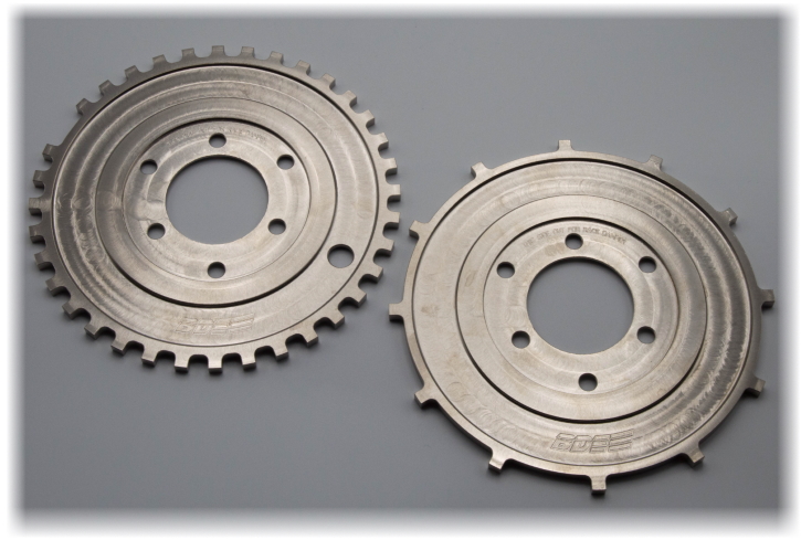
Crank Trigger Teeth - What's the Big Deal? A Little History - 4-Stroke Engine Cycle A 4-stroke engine cycle is defined as: Intake, Compression, Power, and Exhaust and takes place over two revolutions of the crankshaft, or 720° of rotation. The camshafts rotate at half of the crankshaft's speed, so they rotate once per engine cycle. Because a 4-stroke engine needs one ignition event for every engine cycle, early 4-stroke engines were designed to drive their ignition triggering device off of a camshaft and over 100 years later, the Z32's VG was still following suit. The problem with using a camshaft to drive the triggering device is that its position relative to the crankshaft position can oscillate substantially, some people have reported by as much as ±7.5° (crankshaft) in the VG, and this is due to the valve springs pushing against the opening and closing ramps of the camshaft lobes and the slack that can occur between the drive mechanism (timing belt). This is the very reason why a crank-driven trigger is far more accurate than a cam-driven trigger. Crank Triggers, Old and New The only requirement of an old crank trigger was that it needed to have half the trigger teeth or magnets of the engine's cylinders, so a 6 cylinder only needed 3 evenly spaced triggers to be able to fire all cylinders with perfect accuracy. Older crank triggers were designed to fire the ignition at the exact moment when a trigger passed its sensor and had no ability to control or advance ignition timing while the engine was running. Add an ECU, with the capability of quickly calculating timing-related events, and the modern-day crank trigger becomes reference points that provide location signals so the ECU can keep track of crankshaft position. The ECU constantly calculates where the crankshaft position is after the last crank trigger signal, and then verifys position when the next trigger signal arrives. Any differences between calculated position and real position are due to changes in RPM that occur after the last trigger event and the best way to reduce these errors is to reduce the time between trigger events. To accomplish this, more trigger teeth are added to a crank trigger wheel destined for use with an ECU. This increases the number of reference points per revolution, which reduces the time between triggers and improves the overall accuracy of the calculated ignition and injection events to near perfection. Crank Trigger Teeth Numbers Explained 12+1 - "12" is the number of teeth on the crank trigger wheel and "+1" is a single tooth cam sync/home signal. 36-1+1 - "36" is the number of teeth on the crank trigger wheel if none were missing, "-1" is the number of teeth missing, and "+1" is a single cam sync/home signal. Missing Teeth? By removing one or more teeth from the crank trigger wheel, a unique identifier is created that occurs on every crankshaft rotation. A benefit of the missing tooth being on the crank wheel is it's location with respect to the remaining crank trigger teeth is physically locked in and is not affected by cam oscillations. When used by itself, a missing tooth crank trigger will allow semi-sequential injection (two injector openings per engine cycle) and wasted-spark coil on plug ignition (coils for cylinders that are 180° apart in their firing order are paired and fired at the same time). When used with a cam sync/home signal, sequential injection and coil on plug ignition is enabled. Cam Sync/Home - What Does This Do? This is a cam-driven, single tooth trigger that identifies a full 4-stroke engine cycle and provides a signal that allows the ECU to enable sequential injection and coil on plug ignition. ECU Trigger Patterns
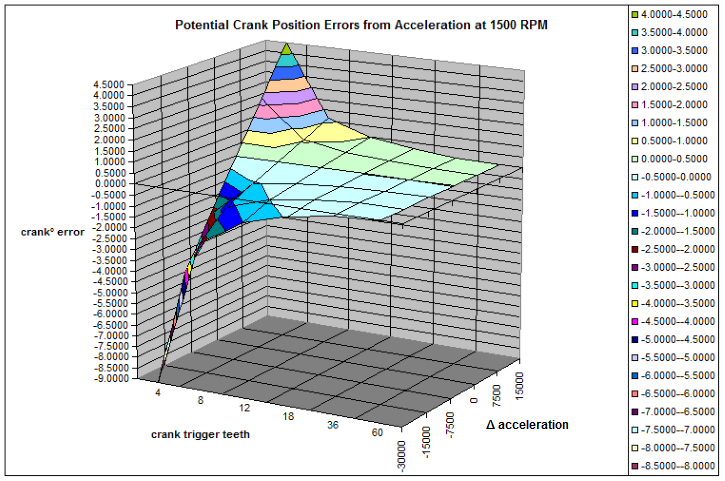
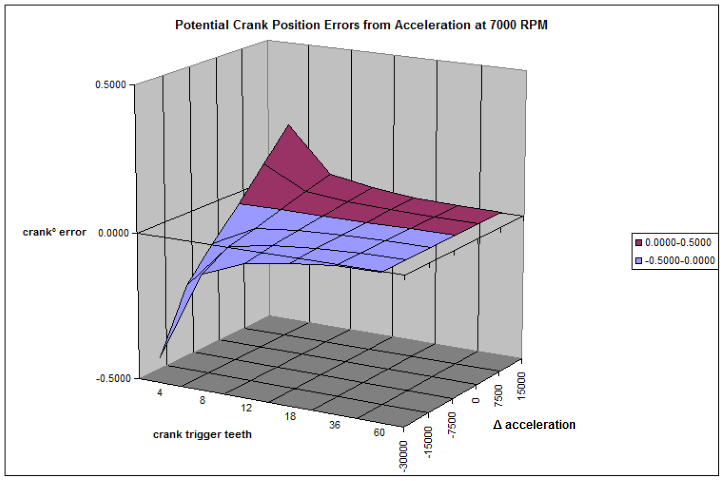
Most ECU manufacturers program their ECU to accommodate multiple different trigger patterns. The BDE 12+1 tooth and 36-1+1 tooth crank trigger wheels each work with distinctly different trigger patterns, both of which are discussed below. Which One Is Better? First, simply converting from the cam-driven CAS to any crank trigger will result in the highest gain in accuracy - any benefit of going from 12 tooth to 36 tooth depends more upon your ECU than anything else. Before we get too far into this, let me just say that if you have a Haltech Platinum Pro Plug-In ECU, your only crank trigger option is the 12+1. Haltech only offers two trigger options for this ECU, the "Nissan VG30" for the OE CAS, and "Multitooth 24 and 1" for a CAS with the AEM 24+1 CAS disc installed. Fortunately, a cam-driven 24+1 trigger pattern is the same as a crank-driven 12+1 trigger pattern and your Platinum Pro can easily take advantage of a crank trigger's higher accuracy. If you're still worried you might be missing out on even more accuracy, read on... Crankshaft Position - It's All Just Math... But First, You Must Sync the Timing Knowing where the crankshaft position is relative to TDC is the entire goal of any trigger device, but how does it do this? When you setup your ECU, you must sync the physical ignition timing of cylinder #1 to be the same as what the ECU is programmed to deliver - until you do this, the ECU will never have any clue where the crankshaft position is. This is easily accomplished by disabling the injectors to prevent flooding the engine and locking the timing to 0° in the ECU's software utility. Then have a friend crank the engine over while you watch a timing light to see where the spark event occurs. Adjust the "Trigger Angle" (Haltech name) or "Ignition Sync" (AEM name) in the ECU's software to make the timing light signal equal 0° and you are close to being done. Re-enable the injectors and start the engine (you may need to change the locked timing to 20°BTDC to get it to idle), recheck that the timing is exactly as you have it locked at in the ECU's software utility and you have successfully synced your timing to the ECU. Remove the locked timing entry and you are ready to start tuning. Position Every time a crank tooth passes the sensor, the crankshaft position is accurately registered to the ECU - but the real trick is figuring out where the crankshaft position is between the crank teeth. To get crankshaft position between crank teeth, the The ECU takes the last three measured trigger events to calculate the velocity and acceleration and then uses a counter/timer to predict the crank position for ignition and injection events that all occur between the trigger teeth. Velocity (RPM), a Closer Look To measure RPM the ECU starts a high-precision counter/timer when it receives a signal from the sensor that a tooth has passed it. When the next tooth passes and the ECU receives its signal, the timer is stopped, the count is recorded, the timer is reset, counting begins for the next trigger event, and this process repeats for every single tooth on the trigger wheel. To calculate the RPM between two trigger teeth we need to know the total teeth on the trigger wheel and the time between each tooth. Let's look at a wheel with 12 teeth, all equally spaced, and a timer count of 0.003125 seconds (3.125 mS). RPM = 60/(12 x 0.003125) RPM = 1600 Where: 60 = seconds/minute 12 = teeth/rotation 0.003215 = seconds/tooth A timer count of 0.000833 seconds (0.833 mS) would be 6002.4 RPM with a 12 tooth trigger wheel. Using the above RPM formula we can quickly see that a higher tooth count trigger wheel will take less time between trigger events and this will result in more RPM calculations for every revolution and therefore a higher RPM resolution. Acceleration What is a real-world acceleration rate? And does it matter if the engine is free-revving or under load? Obviously an engine is going to accelerate quicker when free-revved versus under load, but how important is timing accuracy when an engine isn't under load? A good example of extreme acceleration under load is a 1900 WHP GT-R which accelerates in first gear at roughly 9260 RPM/second, and in high gear (1:1) at 1000 RPM/second. But while up shifting, the crankshaft decelerates at a rate of -42500 RPM/second (my thanks to Tony Palo from T1 Race Development for this data). To calculate the engine's acceleration rate, the ECU needs no less than three trigger teeth - the time between #1 and #2 sets the baseline velocity and then the time between #2 and #3 is used to see if the velocity has changed, or accelerated. After that the ECU can only assume the acceleration to the next tooth will be the same as the last measured acceleration. It is important to remember that the ECU calculates and predicts the crank position when it fires a spark plug or injector. This prediction is based upon the last measured RPM and acceleration, and the potential for an error in calculated position can occur if there is a change in acceleration after the last trigger event. Acceleration can be a Jerk Physics' term for the rate of change in acceleration is "Jerk," and the larger the Jerk, the larger the error in crank position calculation. Let's look at what happens when an engine is subjected to varying degrees of Jerk at RPMs of 1500 to 7000, with crank triggers from 4 teeth all the way up to 60 teeth, and changes in acceleration rates (Jerk) from -30000 to +15000 RPM/second. Drawing from simple physics, I'll use a formula to calculate a linear change in velocity from a measured initial velocity, acceleration rate, and time and then compare to a recalculation of the same equation with a new, increased or decreased acceleration rate: vf = vo+at2 Where: vf = velocity final (RPM) vo = velocity initial (RPM) a = acceleration rate (RPM/second) t = time (seconds) We can take the difference in calculated velocities and convert that to crankshaft position in degreees since we know there are 360° for every rotation, and 60 seconds for every minute. position = (V1-V2)t x (1 minute/60 seconds) x (360°/1 Rotation) Where: V1 = velocity from known acceleration rate V2 = velocity from changed acceleration rate t = time (seconds) 1 minute/60 seconds = units conversion for minutes to seconds 360°/1 Rotation = units conversion for rotations to degrees For simplicity, I've run the calculations for 1500, 3000, 5000, and 7000 RPM and graphed the results below. Positive numbers means the crank position will be ahead of the predicted position, so the timing would be retarded - likewise, negative numbers means the crank position will be behind the predicted position and timing would be advanced.
Conclusion
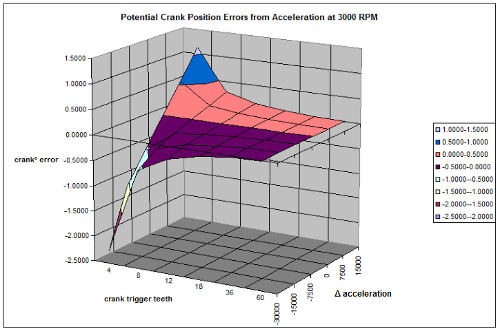
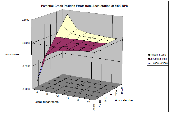
It's clear from the graphs that as the RPM increases, the amount of potential error diminishes. Also, we can see that the 12 tooth error at 1500 RPM is below 1° for changes in acceleration rates of ±15000 RPM/second. Yes, the 36 tooth has less of an error than the 12 tooth, but keep in mind these scenarios assume the worst case where there is a change in acceleration after the last tooth event recorded by the ECU. I will argue that the timing error difference between 12 teeth and 36 teeth is not worth worrying about for two reasons: In my opinion, the improved timing accuracy of both is worlds above any cam-driven trigger device. The main difference between the 12+1 and 36-1+1 crank triggers is the care that needs to be taken when setting up the cam sync/home location relative to the crank trigger teeth - the 12+1 should be positioned as close as possible to being in the center of two crank trigger teeth, while the 36-1+1 only needs to be setup so the cam sync/home does not occur when the missing tooth section is passing the crank sensor.
|
|||||
|
BDE products are designed and intended for off-road racing use only ©2008-2026 Brett Dempsey Engineering
Email BDE
This Website Optimized
for 1366x768 and Higher Resolutions |
||||||